


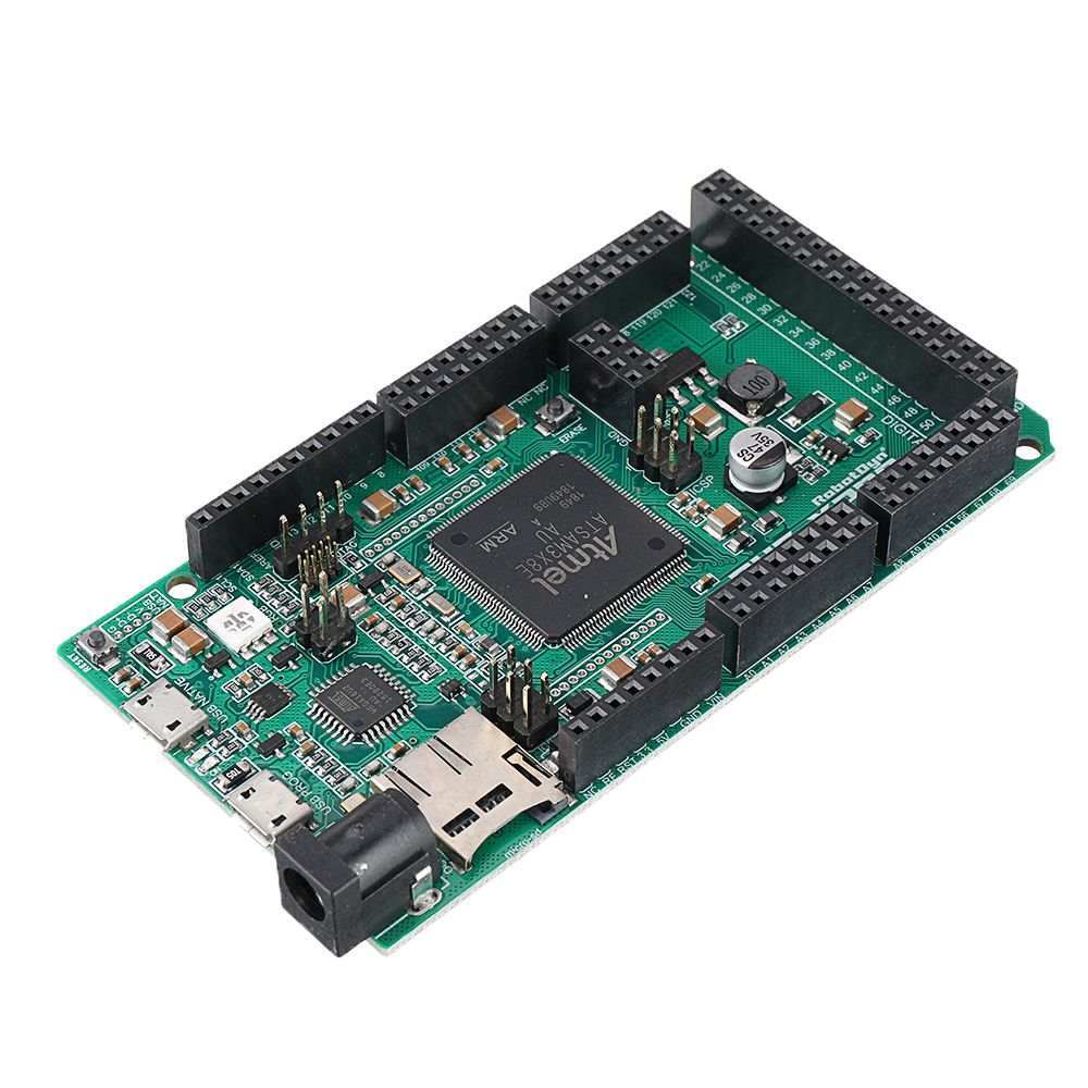
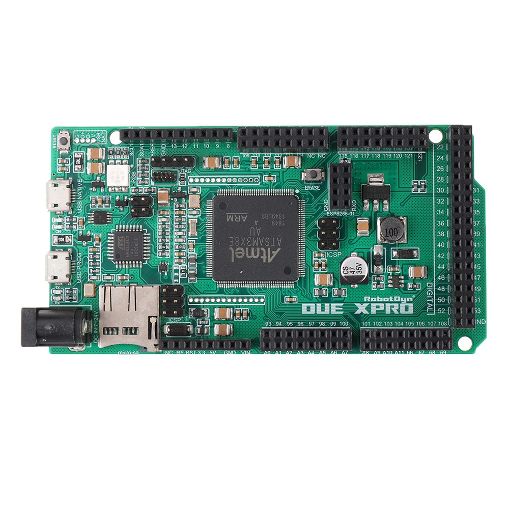
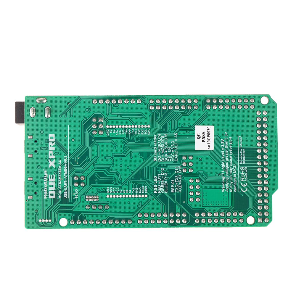
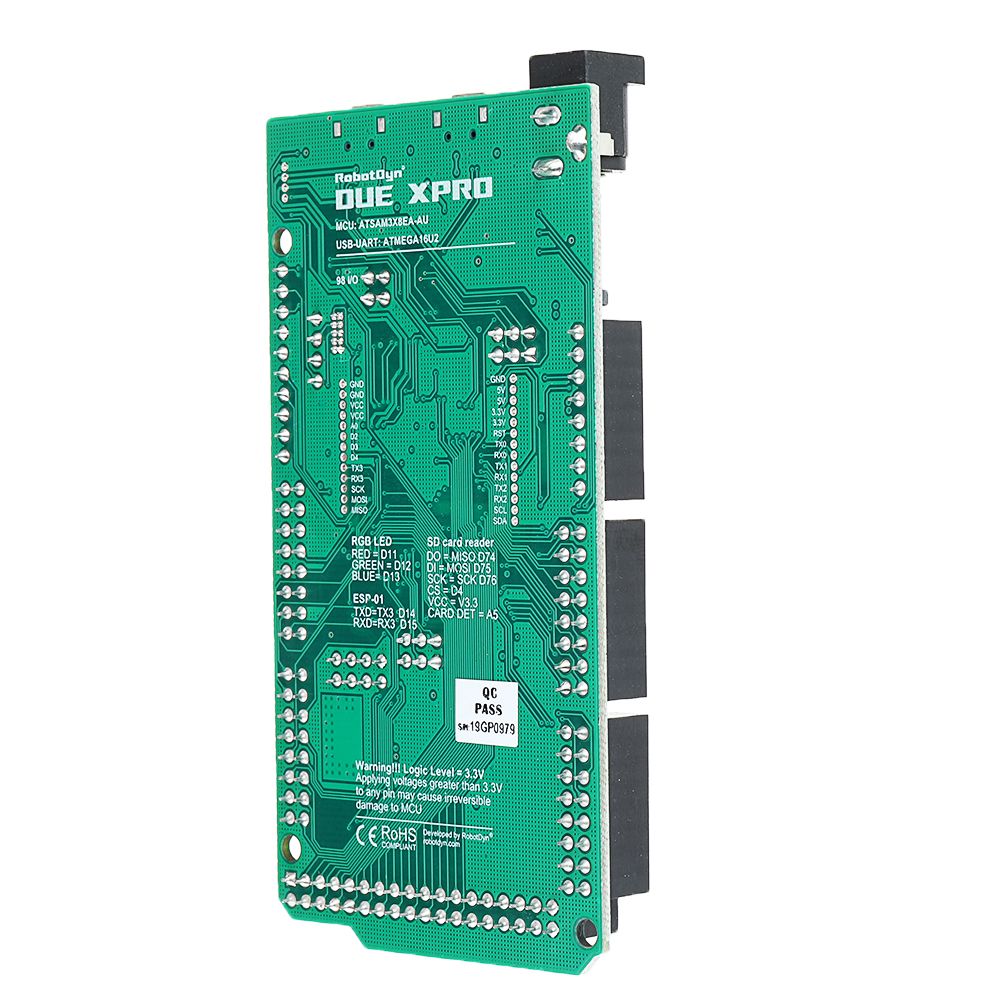
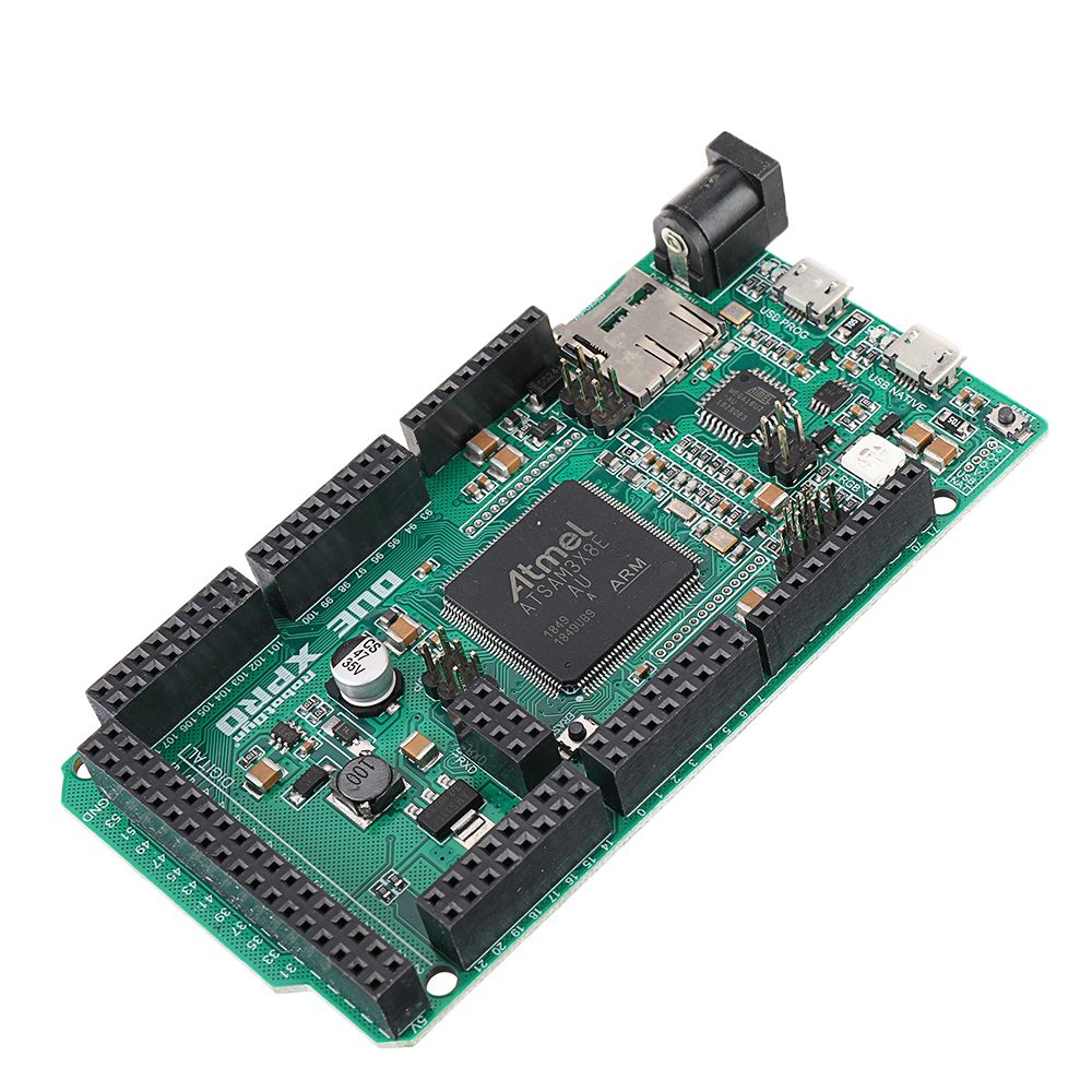
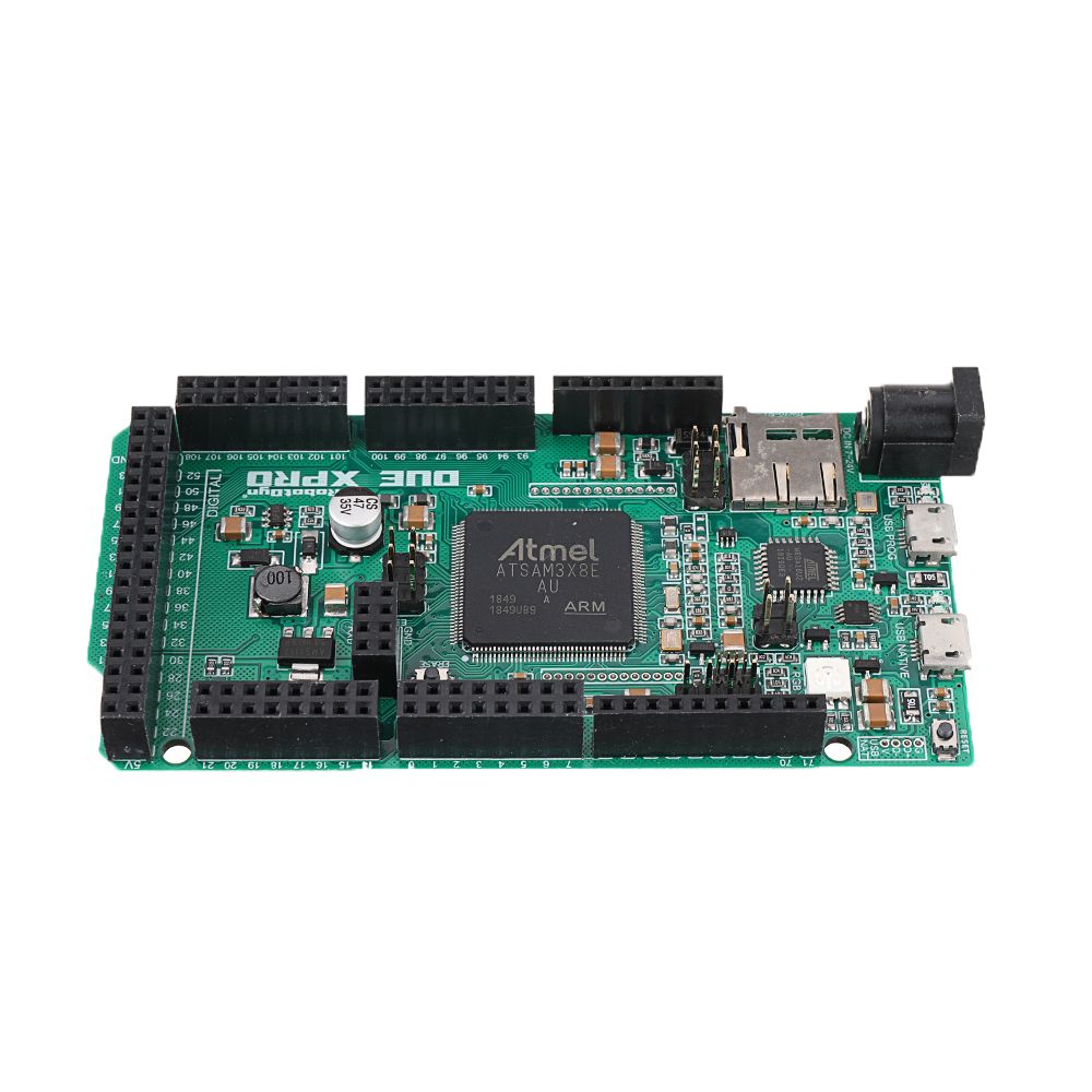
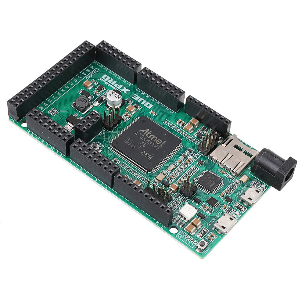
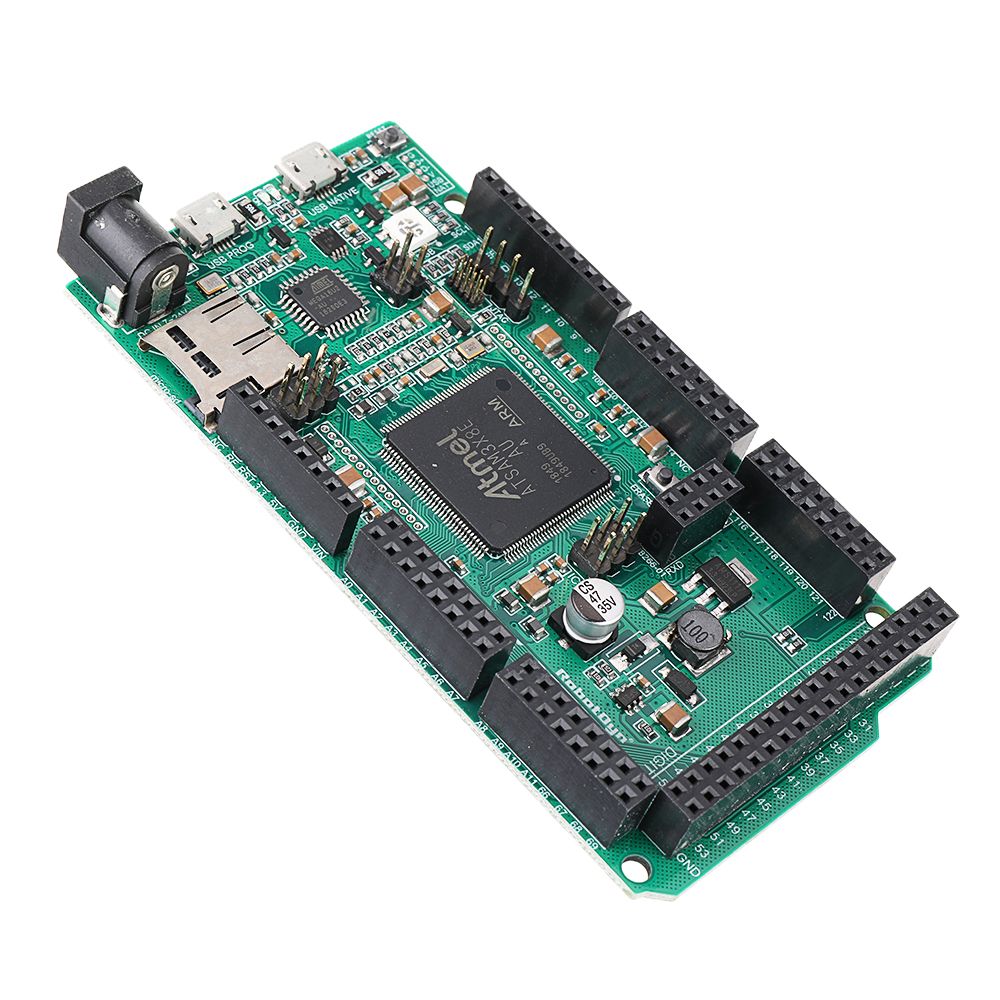
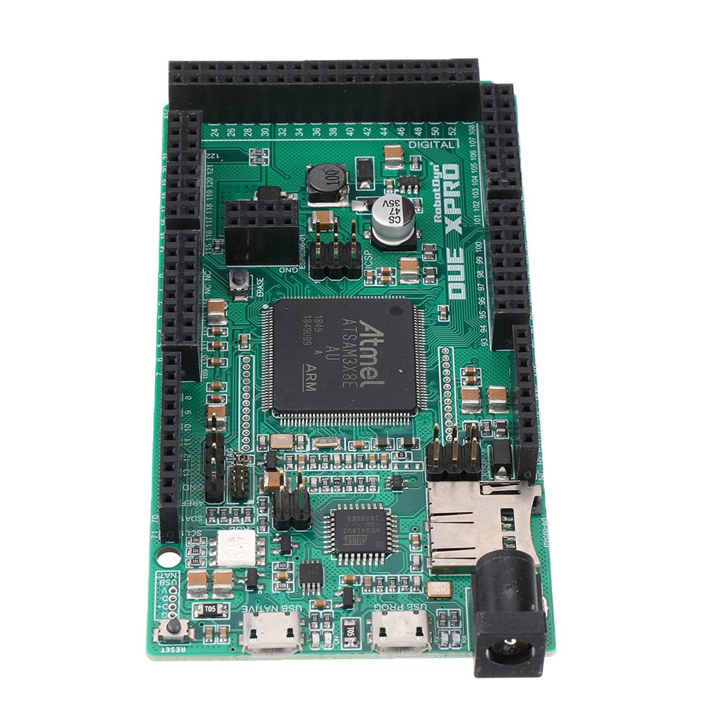
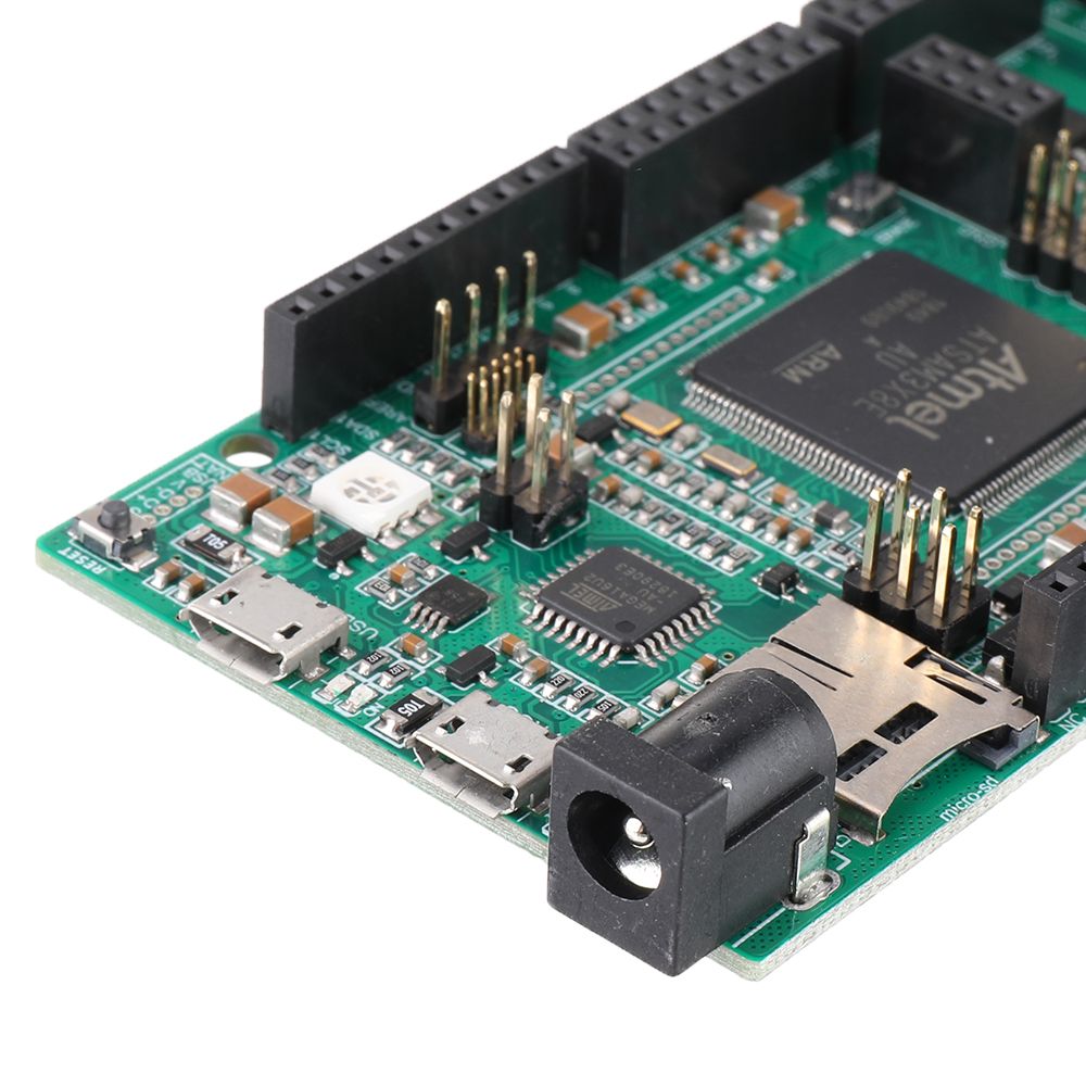
DUE XPRO Cortex ATSAM3X8EA-AU 98 I/O SD Reader RGB LED ESP-01 Socket Development Board


- Stock: In Stock
- Model: EB0041733
- SKU: EB0041733
- Voltage: DC5V
Precise details:
Package includes:
1 x Development Board
Package includes:
1 x Development Board
Shipping Time
After you successfully placed an order at RenhotecIC.com, you will receive a confirmation email with your invoice. Once your order is shipped, you will be emailed with the tracking information of your package. Also, you can choose your preferred shipping method during the checkout process. Kindly advise: please select DHL/FedEx if you need our product urgently.
The timeline of the whole shipping process is shown below:

The total delivery time is calculated from the time your order is successfully placed to the time received. Total delivery time is broken down into processing time and shipping time.
Processing time: The time it takes to prepare your item(s), includes preparing your items, performing quality inspections, and packaging for shipment. Normally, the processing time is 1-3 days (Only include Monday to Saturday ) after getting your order.
Shipping time: The time for your item(s) to travel from our warehouse to your destination. The shipping time depends on the shipping method you chose. Please refer to the shipping rate section for details.
Shipping Rates
You could choose the shipping method based on your preference during checkout, different shipping methods will apply different rates and shipping times. Please check the following chart for detail:
You could choose the shipping method based on your preference during checkout, different shipping methods will apply different rates and shipping times. Please check the following chart for detail:
| Shipping Method | Shipping Rates | Shipping Times |
| Flat Shipping (Promotion) | $10 | About 5-30 Working Days to Worldwide (Only include Monday to Saturday ) |
Standard Express(0.5KG starting price listed) | Based On Weights | About 5-15 Working Days to Worldwide (Only include Monday to Saturday ) |
Priority Express (0.5KG starting price listed) | Based On Weights | About 3-7 Working Days to Worldwide (Only include Monday to Saturday ) |
In addition, the transit time depends on where you're located, the shipping method you choose, and where your package comes from. We will keep you informed of any problems here to help you get your order as soon as possible.
If you want to know more information, please contact the customer service by contact form or sales@renhotecic.com. We will settle your problem as soon as possible. Enjoy shopping!


 ESP8266 ESP-12E + WiFi Motor Drive Expansion Board")

